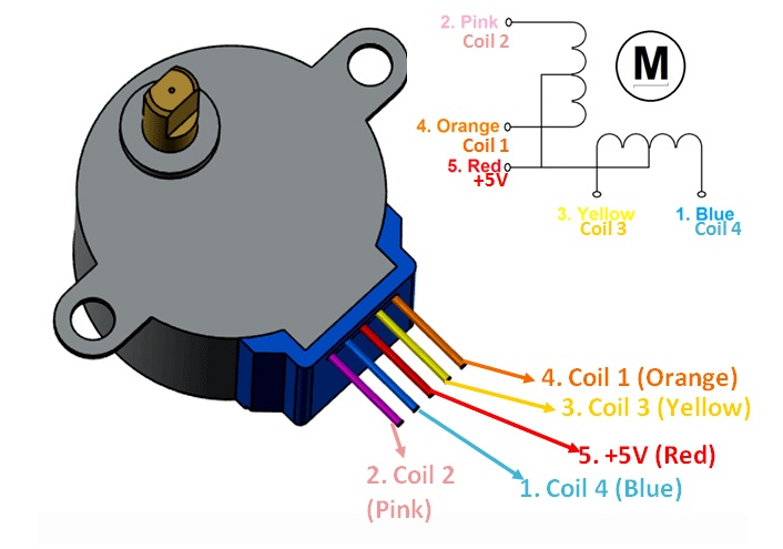
This Motor has a total of four coils. One end of all the coils are connect to +5V (red) wire and the other end of each coil is pulled out as wire colors Orange, Pink, Yellow and Blue respectively.These four wires are alternativly grounded for rotation.
28BYJ-48 Stepper Motor Technical Specifications
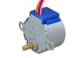
The most commonly used stepper motor is the 28-BYJ48 Stepper Motors. This type of motor can be found in DVD drives, Motion cameras and other devices. These motors has a 4 coil unipolar arrangement and each coil is rated for +5V hence it is relatively easy to control with any basic microcontrollers. These motors has a stride angle of 5.625°/64, this means that the motor will have to make 64 steps to complete one rotation and for every step it will cover a 5.625° hence the level of control is also high. However, these motors run only on 5V and hence cannot provide high torque.
These stepper motors consume high current and hence a driver IC like the ULN2003 is mandatory. To know how to make this motor rotate we should look into the coil diagram below.
There are four coils in the motor and one end of each coil is tied to +5V (Red) and the other ends (Orange, Pink, Yellow and Blue) are taken out as wires. The Red wire is always connected to a +5V supply. This +5V will be across (energize) the coil only if the other end of the coil is grounded. A stepper motor can be made to rotate only if the coils are energized (grounded) in a logical sequence. This logical sequence can be programmed using a microcontroller or by designing a digital circuit. The sequence in which each coil should be triggered is shown in the table below. Here “1” represent the coil is held at +5V, since both the ends of coil is at +5V (red and other end) the coil will not be energised. Similarly “0” represents the coil is held to ground, now one end will be +5V and the other one is grounded so the coil will be energised.
Sequence to Rotate in clockwise Direction


