Product Description:
Description:
- The PWM transfer voltage module LC-LM358-PWM2V converts the PWM digital signals into 0 to 10V analog signals.
- It can be used as signal interface switching for PLC or other industrial control boards. The output voltage is regulated by adjusting the duty ratio of the PWM.
Features:
- MCU embedded technology
- Easy to operate, fine tuned by potentiometer
- Select the PWM signal input level range through shorting link
Parameter:
- Operating Voltage: - DC 12V to 30V
- Operating current approx: - 100mA
- PWM Receiver Frequency: - 1KHZ to 3KHZ
- PWM signal input level range: - For peak levels between 4.5V and 12V install short cap in ‘5V' position. This level is used for normal controller or 5V MCU. For peak levels between 12V and 24V install short cap in 24V position. This level is used for normal PLC controller
- Conversion range: - 0% to 100% PWM for 0 to 10VDC
- Allowable error: - 5%
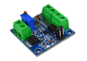
Hardware Interface:
| Specifications |
|
|
| Conversion error |
|
1 to 3% |
| PWM amplitude selectable |
|
4.5 to 12V |
| |
|
12 to 24V |
| Conversion range |
|
0 to 100% PWM for 0 to 10V DC |
| Pin definition |
|
|
| VCC |
|
12 to 30V DC |
| GND |
|
Ground |
| VOUT |
|
Output voltage: 0-10V |
| GND |
|
Output voltage ground |
| PWM |
|
Positive of PWM signal |
| GND |
|
PWM ground |
Operation instructions:
After power on, without input signal, the output will be 0V.
When using the module for the fist time, calibration of the output is recommended. Set the shorting link to the appropriate setting for the input amplitude be used. Input a 50% duty ratio signal to PWM/GND.
With a frequency between 1KHZ and 3KHZ, measured VOUT and GND with a multimeter.
Adjust the potentiometer to obtain a reading of 5.00V on multimeter.
The calibration is frequency specific. If the frequency of the PWM signal is changed the module should be calibrated for the new frequency.